
simple cost effective darlington amplifier
This amp had its genesis in the Widlar (pronounced Widelar) circuit below published in the LM308 application note of 1969 An interesting analysis of the LM308 here:
http://www.righto.com/2016/12/inside-lm108-op-amp-superbeta.html
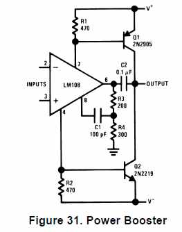
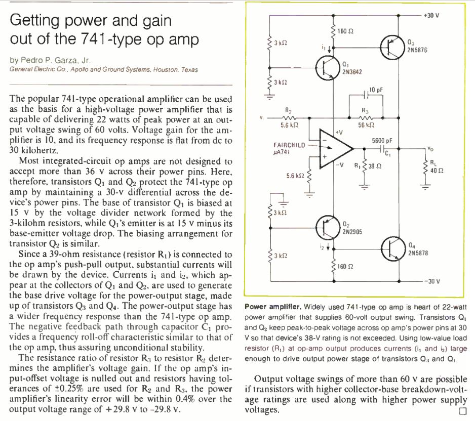
The op amp deliberately has a low resistance load R3 and R4 which means a useful current flows into or out of the transistor bases. The current is amplified by Q1 and Q2. Note the only connection between the op amp output and the actual output is a feedforward capacitor. There is no provision to set the bias for Q1 and Q2 so there will be crossover distortion. I thought why not use a respectable op- amp and a pair of darlingtons to make a hifi amp. Apparently the concept dates back to 1973, when Garza published it using a 741. US patent 3919655 explains some of the issues.
Note C1 is a feed forward capacitor
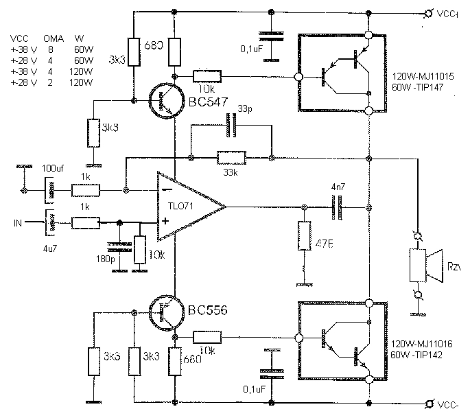
I suspect this is a modified circuit from that paper with a TL071 substituted for the original 741 and Darlingtons substituted for the output transistors. The 10k base stoppers will heavily slug the high frequency response and the 47 ohm load resistor looks too low.
Steph on the Diyaudio site came up with a model of the Ne5534 op-amp which I am using as the basis of a simple power amp also using BDX33 & BDX34 darlington output devices. I came across a couple of interesting pieces in my research which I thought I would share with you
http://www-f9.ijs.si/~margan/Articles/Class_B_Dist.pdf
Interesting letter on this from the late Les Sage (my fellow author in the Audio Conversions magazine of the 90’s)
http://gsjournal.net/Science-Journals/Journal%20Reprints-Relativity%20Theory/Download/3272
The NE5534 dates back to 1978, interesting comparison here with the LM318:
http://www.waynekirkwood.com/forum/php/viewtopic.php?f=12&t=454&sid=878a7199d2f6a4f07e6f04ca93500336
Apparently the NE5534 was originally the TDA1034 which dates back to 1975 and was designed with input from Rupert Neve of mixer fame.
Paul Kembles site is an excellent view of the various designs and topologies.
http://www.angelfire.com/sd/paulkemble/soundindex.html
if you thought Paul’s site covered all the topologies try this:
https://sites.google.com/site/francisaudio69/6-lamplificateur
My amp is bucking frilliant compared with these! (thermal issues you understand)
Good video on op-amps with booster transistors not my topology but similar issues
https://www.youtube.com/watch?v=YdSFhRpvil4
Good explanation of the crossover issues with power op-amps:
Kendall, the filter guru, has an interesting article on the output topology, and a ref. to the ETI Powerslave amp, knew I had seen the circuit somewhere before.
The actual design would be based on this
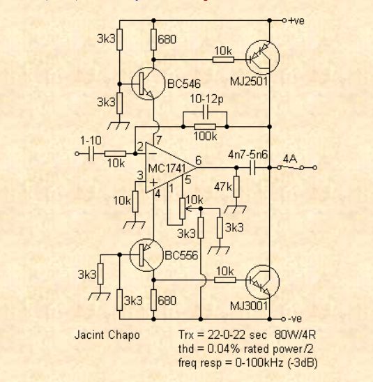
By the way the 47k load resistor in the above looks too large to draw enough current to make the circuit work, should be 47 ohms. The great and the good discuss the topology here:
http://www.electronicspoint.com/anyone-familiar-topology-t23796.html
Found darlington models here
http://ltwiki.org/index.php5?title=Components_Library
At the moment I have modeled the design in Spice but will not publish it until I have tried it in practice. Issues would be crossover distortion and thermal tracking of the output device quiescent current. I have at present modelled it OK and now need to heat up the soldering iron to see if it works. I have lost the computer I did the modelling on but I had to have 820 ohm base stopper resistors to make the model converge.
Update: Finally got around to trying this out. All I can say is that Stephs model seems to be good in that the modelled amplifier when built behaved itself. i.e did not oscillate! Had to add 0.22uF supply decoupling capacitors to stop some oscillations but this should be standard practice. With a feedback amplifier you need a dominant pole for stability. The output capacitance of the darlingtons creates the neccesary roll-off. PNP darlingtons have more capacitance and give more stability than the NPN type, so a base stopper resistor is included on the NPN one.
I found this technique which enables me to look at the open loop gain and phase:
http://www.planetanalog.com/document.asp?doc_id=528133
One of these days I will sort the thermal tracking out.
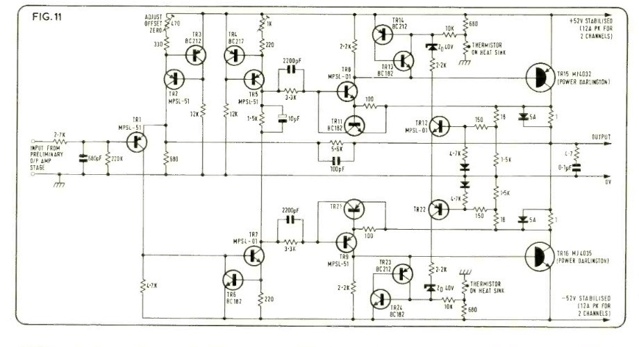
Update:
I first outlined the idea in post #18 http://www.diyaudio.com/forums/showthread.php?t=71403&referrerid=11997 however, the scheme has changed somewhat, with NTC thermistors replacing the schottky diodes and common base current followers replacing the zener level shifters. Steph’s NE5534 spice models on Diyaudio kick-started new activity and the Koroda design gave the common base followers. Steph’s model accurately reflected the output load current into the supply lines enabling modeling of the topology.
The technique has been successfully used industrially but there is a crossover distortion issue with the raw design. When you sort that out, you run into a thermal problem of keeping the quiescent current constant over temperature. I have solved that with thermistors. I did a thermal analysis using this:
http://www.ecircuitcenter.com/Circuits/therm_ckt1/therm_ckt1.htm
The tempco worked out at 4.5mV per degree C, close to the theoretical 2 X 2.2mV needed to compensate the 2 darlington Vbe’s, tempco values being negative of course.
Thermistors are a time honoured way of solving the crossover problem, article from 1960:
The amp seems stable, without needing compensation components liberally scattered over it. Indeed it seems more stable in practice than in simulation which is unusual (for me, anyway). Initially my experiments were with BDX33/34 devices and the results were so good I decided to scale up to TIP142/147 devices.
This would be a discrete component alternative to the LM3886. It also does not have the protection circuits of the IC which some claim are audible. The amp using the BDX pair would be a discrete alternative to the TDA2030/2050 series and as it has better high frequency characteristics would be good for a tweeter driver in an active speaker.
More testing has revealed a dependency between supply volts and quiescent current setting. I will use a zener diode and darlington as a crude series power supply to get around this problem. See Rod Elliot’s el cheapo project for the power supply circuit. I tried a constant current between the darlington bases but the thing oscillated. Also modelling the high frequencies shows a problem, at 13KHz, the op-amp output waveform changes. In practice though this does not happen i.e the thing performs better in real life than the sim. This tells you that the IC and darlington models need tweaking but I do not have the time or inclination for that. My feeling is that the linearity and frequency response of modern darlingtons is better than the models. My intention is to use 6 of these as output amps for my DCX2496.
One issue with the design is that the quiescent current of the NE5534 rises with temperature, so the quiescent current of the output transistors rises too. However not enough to lead to problems. This characteristic is not specified in the NE5534 data sheet. I had problems if the supply voltage to the 5534 was more than 15V though. The LME49870 has extremely low distortion and is available at a reasonable price so would be worth a try in this. The ultimate amp using this topology would be LME49870 and SAP16’s which have a higher SOA than the TIP’s. The SAP’s would have the internal temp. comp. diodes disconnnected, of course. The LME49870 is used on headphone amps and this topology (using single transistors rather than darlingtons) could be used to boost its output using BD437/438 to make a powerful headphone amp or Ipod dock. An extension to the topology here:
Another 405alike:
http://www.constructor.bg/mk/Amp.htm
How to do it with FET’s
http://skywired.net/blog/2012/03/cool-chip-lt1970-power-op-amp-with-current-limit/
Or these
http://ddata.over-blog.com/xxxyyy/1/74/30/05/schemateque/Ampli40w_1980.pdf
http://www.electroschematics.com/4/mosfet-audio-amplifier-irf9530-irf530/
The famous 1979 Siliconix DA76-1 sadly the output devices are NLA. This has nothing to do with my theme but the circuit is so elusive I thought I would publish it.
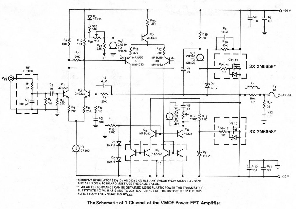
The TIP darlingtons first saw the european light of day at TI’s Bedford plant in the late sixties so they are 40 years old. Apparently E-beam lithography was pioneered at Bedford and not a lot of people know that! In Aug 1985 TI were offering “breadboarding in silicon” using the technique. I do not think the process was used on the TIP devices though. Now made by ST and others, the ST ones having a new process “planar base island” or is that hype for how they have always been made? But it would be worth using the new ST ones in case they are better. Incidentally Hardcastle and Lane wrote some amplifier application notes and articles for TI in the late sixties/early seventies and helped popularize the use of their devices. Their Wireless World article in Oct 1970, A high power amplifier, may be the first use of back to front output power transistors i.e. common emitter. Actually the output stage is the common CFP type as can be seen below. In the text they mention the then new TIP35/36 which were more expensive than the power devices in the diagram!
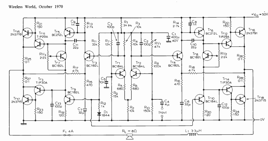
I got this from an excellent Wireless World archive at:
http://www.americanradiohistory.com/Wireless_World_Magazine.htm
The circuit in the article below misses out Cdom! So it would probably oscillate.
Incidentally the above archive now has ETI (Electronics today International) magazines as well.
An op-amp based amplifier, the “Texan” was popular in the UK at the time and was designed by Mann of TI. Talking of TI Bedford, just heard this extraordinary apocryphal story, Texas Instruments at Bedford used a large batch of reject transistors as hardcore for a driveway. Clive Sinclair found out about this, presumably through industry contacts, and rather than shrugging his shoulders at a missed opportunity negotiated a price for digging the whole lot up again! Reminiscences of TI Bedford:
http://www.kguttag.com/2013/08/10/if-you-havent-tested-it-it-doesnt-work/
I have just discovered the articles by Samuel Groner on the transimpedance VAS which of course this is, But Samuel uses a conventional output stage rather than letting the transistors be the output stage as well. Samuel has done a discrete component version of the NE5534 here:
http://groupdiy.com/index.php?topic=57544.0
Compare with the device schematic of the LM1875 given on this datasheet (Q38 is the problem)
http://www.ti.com/lit/ds/symlink/lm1875.pdf
Analysis of Darlington distortion here:
http://www.valveradio.net/index.php/en/home/audio/darlington.html
I recently found a commercial product which uses this topology the Abacus available in Germany, as Abacus are still using the Reider circuit.
http://www.hifi-archiv.info/Abacus/abacusRiede60s/
By coincidence, Abacus make a convolver preamp with a Raspberry Pi and Cirrus Audio card:
http://www.audiovero.de/preamp-14-cleanvolver.php
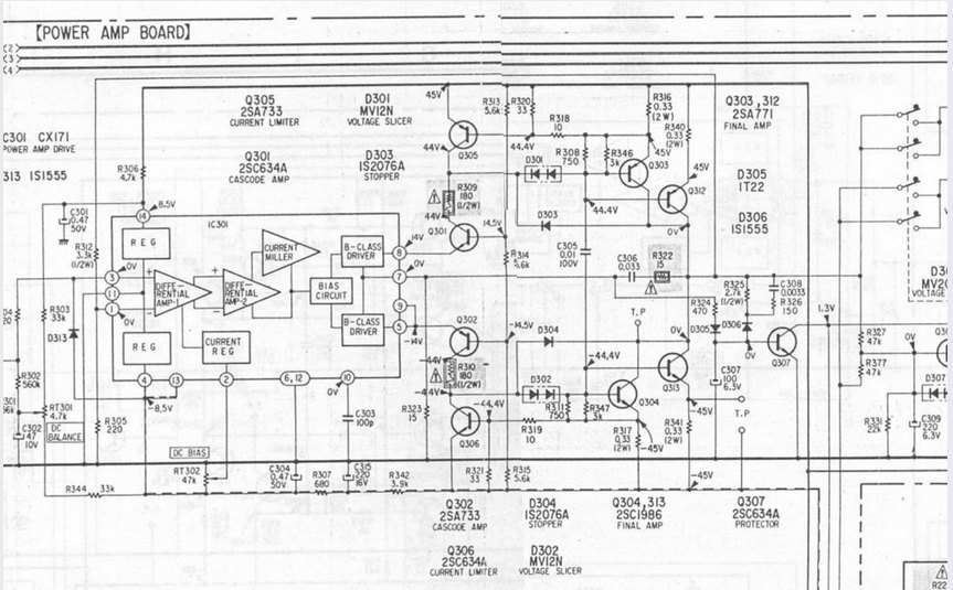
The common emitter output stage is more conmmonplace than I thought. The Sony TA-F5A uses it. Love the current miller! The output stage has not been discussed in any text books to my knowledge.
More on the topology:
http://www.diyaudio.com/forums/solid-state/284760-can-anyone-help-me-explain-circuit.html
http://www.eevblog.com/forum/beginners/non-standard-op-amp-configuration/
You might need my thermistor idea with this:
http://www.tnt-audio.com/clinica/dynamicopamp_e.html
That amp was probably developed from Fig 14 in this app. note from Analog Devices, but dates from the Precision Monolithics days. Incredibly you can still get the parts. Who knew that Precision Monolithics had a UK design centre at Twickenham?
https://www.analog.com/media/en/technical-documentation/application-notes/28080533AN106.pdf
For a discussion on Common Emitter Output stages see Cherry second article
A low distortion common emitter design
https://www.by-rutgers.nl/PDFiles/Amps/SSA35.pdf
To test the amplifier, you might want to use a speaker emulator load rather than a simple resistive load:
http://www.aikenamps.com/index.php/designing-a-reactive-speaker-load-emulator
The above uses rather large reactive components to emulate the low frequency resonance. This uses gyrators to make the reactive components smaller
I remember a puzzling problem for Diyaudio member 5th element whose distortion problem turned out to be the voltage rating of the feedback resistor. Never thought I would come across the thread again but here it is:
http://www.diyaudio.com/forums/solid-state/160061-slones-11-4-blameless-13.html
The fabled Blomley amplifier
JLH amplifier circuit from Studio Sound April 1975 Note output darlingtons, common emitter outputs and thermistor stabilisation. Back issues of Studio sound are on the Americanradiohistory site. I was astonished to find their reviewer Angus Mckenzie was blind!
https://www.stereophile.com/news/011705mckenzie/index.html
The mysterious Losmandy amplifier was an early op-amp based power amplifier which used a discrete component op-amp with a high voltage swing to power a 2N3055 output stage.
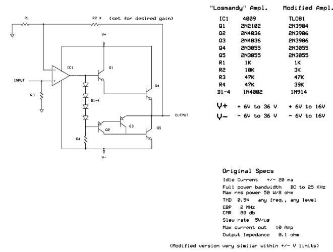
You could eliminate Q2 and D4 but the output swing would not be symetrical.
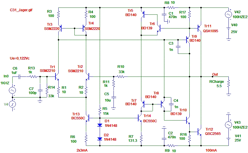
The Dec 99 issue of Electronics World had an article by Wim Jager on a new type of common emitter output stage amplifier with current mode drive. Unfortunately it needs fast output transistors and Tr7-9 need to be mounted on a common heatsink. R7 is adjusted to give 100mA consumption.
Curious amplifier based on the NE5534 with the output shorted out
More complex version, the Arcam A85 fragment of circuit courtesy Arcam
Continued in part 2

Leave a comment