Simple Twin T oscillator
I was reading through a thread on Diyaudio which was exploring distortion measurements. A contributor had linked one of JLH’s masterpieces on spot frequency distortion measurement using Twin T circuits. JLH is John Linsley Hood not John Lee Hooker or Jennifer Love Hewitt, depends on what kind of geek you are!
Spot Frequency Distortion Meter
Why not use matched components from the same batch for both oscillator and notch filter, I thought. Hence the generated frequency and the notch would be at exactly the same frequency, eliminating the need for tuning. So the generator produces say 10KHz and the notch filter removes that frequency leaving a residual which can be measured simply, giving the distortion.
I wanted to come up with simpler circuits and techniques than JLH, using op-amps instead of discrete circuits and to use just one frequency, eliminating all that switching. I came across an oscillator due to Harrison originally on the Theremin site
There is also a good write-up on circuit operation. Would a NE5532 op-amp instead of the original TL072 lower the distortion?
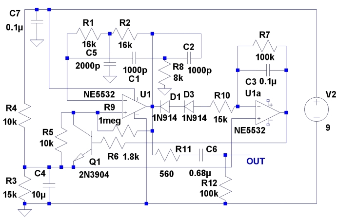
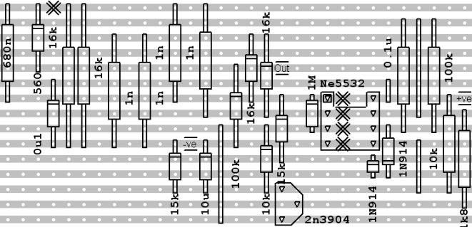
>The positive feedback resistor should be as high a value as possible to eliminate distortion, hence R4 becomes 1M. But you need close matching of the Twin T components to allow this. I matched the components to 0.1%. It is easy from a batch, I selected from a batch of 1% metal film resistors and 2.5% polystyrene capacitors. One of the capacitors C5 is double the other two so the best way to exactly implement that is to put 2 capacitors in parallel. Ditto the resistor R8 that is half the value. With the quoted values frequency is 9.7kHz
The circuit needs an asymmetric potential divider to get low voltage operation.
>As I slowly wound up the supply voltage from zero, the circuit started oscillating at only 3.6V. I was not aware that the NE5532 would operate at such a low voltage. At 5V the output amplitude was established at 2.1V peak to peak and stayed rock steady at that value up to a 15V supply. The distortion mainly 3rd harmonic was down at 0.013%, not bad for a simple circuit.
>I made the AGC gain lower than the original by making R7 100k otherwise the circuit squegged and had a long settling time.
Unfortunately the notch frequency of my active notch filter did not quite match the oscillator frequency, I think this is something to do with the impedances presented to the Twin T network. Also the rejection was a about 55dB so more work required on the notch filter, but that is another story. This idea could be used with Rod Elliots idea here:
https://sound-au.com/project52.htm
In honour of Dick Moore
http://www.tronola.com/moorepage/Twin-T.html
Update. The activity on the TT crossover gave me an inkling on how to tune a Twin –T network. Varying R8 allows the 2 zeros to be coincident and this gives the deepest notch. If R8 is varied from 7.9k to 8.1k the frequency of the notch varies ±30Hz from the nominal 9947 Hz. R8 can be a 7.87k in series with a 100R pot. The pot is varied to achieve the deepest notch on the filter using a rectum paralyser sorry, Spectrum analyser. That frequency is noted. Then the oscillator is tuned to that frequency.
The alliterative Kenneth Kuhn (see Sallen and Key slope) also analysed the
Hall network which is related to the twin T but is easier to tune. I wonder if the saturated transistor stabiliser rather than the lamp stabiliser would work in the oscillator he presents.
https://www.kennethkuhn.com/electronics/design_and_applications_of_the_hall_network.pdf
Another tunable network that could make a tunable oscillator
By the way talking of JLH, there is a worthy analysis of the Class A amplifier here. It is in Italian but you can use a translator
http://piercarlo-audioelettronica.blogspot.com/2019/01/il-linsley-hood-da-10-watt-e-il-suo.html
Good resource on JLH’s articles
https://startfetch.com/jlh/
Other ways of designing op amp oscillators:
Update2
If the T network with 2 resistors and one capacitor is R1C1, the T network with 2 capacitors and one resistor is R2C2 there is a relationship R1C1=4R2C2. So R1 can be 30k and R2 7.5k and the capacitors are equal. If C1 and C2 are 750pF the frequency of the notch is 10003 Hz. Alternatively the resistors can be the same and C1 is 4 times C2, so you can tune the notch with a 3 gang pot.


Leave a comment